| Home | Register | FAQ | Members List | Calendar | Today's Posts | Search | |||
![]() |
![]() |
|||
| Social Groups | |||
![]() |
Registered
Members: 19,823 | Total Threads: 40,095 | Total Posts: 471,118 Currently Active Users: 3042 (0 members and 3042 guests) Welcome to our newest member, BuddyInons |
|
|
![]() |
|
|
Thread Tools | Display Modes |
|
|
#1 | |
|
Grown up member
Classic Audi Club Member
Join Date: Sep 2007
Posts: 253
|
After seeing Tony's mightily impressive results I thought I'd have a go at some headwork. This are by no means finished shots - indeed this is a spare head I intend to slice up - but I'm keen for a steer as to whether or not i'm working the right areas and/or if I have the right tools.
From a bit of reading and then trying to apply it to our engines it would seem that the areas in which gains can be made are to de-shroud the valve and then open up the throat (slightly upstream). ![]() This is the carbide cutter I was using to work the throat area: ![]() I'm a bit unsure as to how much de-shrouding you can do but am under the impression that you can ease the flow path so long as you stay within the lines (so to speak) i.e. the area sealed by the gasket: ![]() ![]() The set of carbides I have comes with the usual shaped bits, though I have to say that I am surprised how easily they remove material from the head even on a very low drill speed. I mean, I understand that the final finish isn't made with these cutters but it would be nice to know i'm at least starting with the right tools and approach! Comments welcome ![]() |
|
|
|
|
|
|
#2 |
|
Grown up member
Classic Audi Club Member
Join Date: Sep 2007
Posts: 253
|
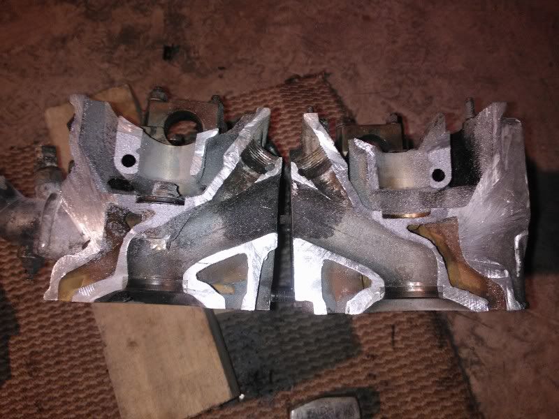
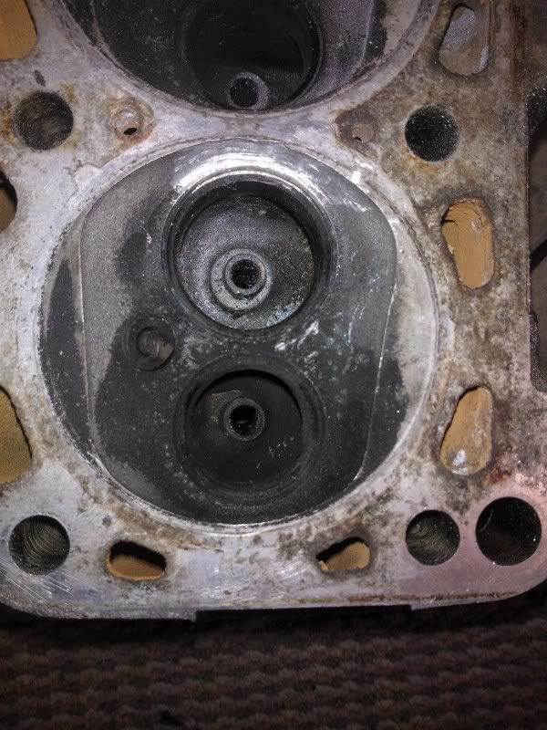
Did a bit more last night; namely sectioning the head to understand exactly what shape the intake port has and to help understand where the lumps and bumps are.
After the final cut (bang on the deck to seperate!): ![]() 
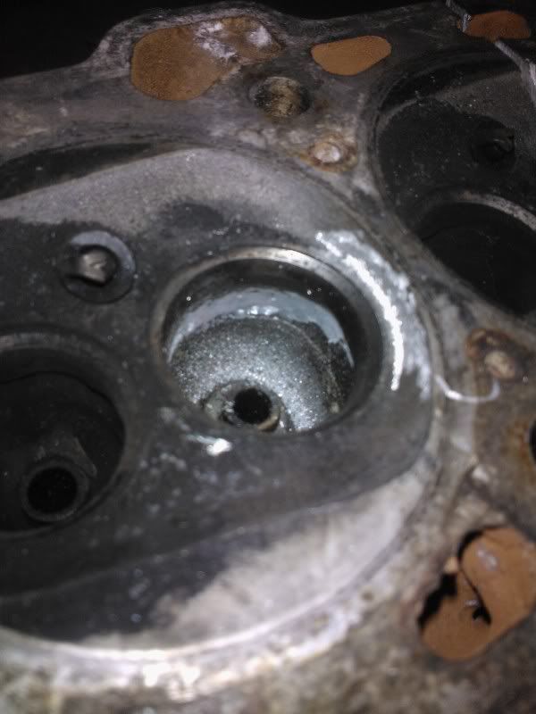
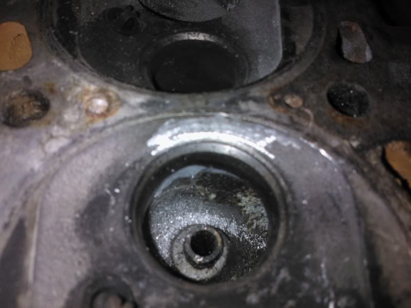
It's amazing the difference between how it looks and how it feels with your finger; even on the ports which are still intact there's a marked step at the valve seat interface both on the short side and far side. What's clearly visible is the throat of the intake port, which to be honest I thought would be closer to the valve, though perhaps rather un-ideally it's almost a bloody right angle - am sure the charge loves that! ![]() 
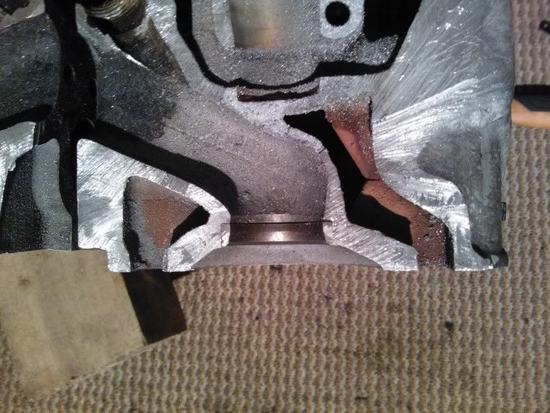
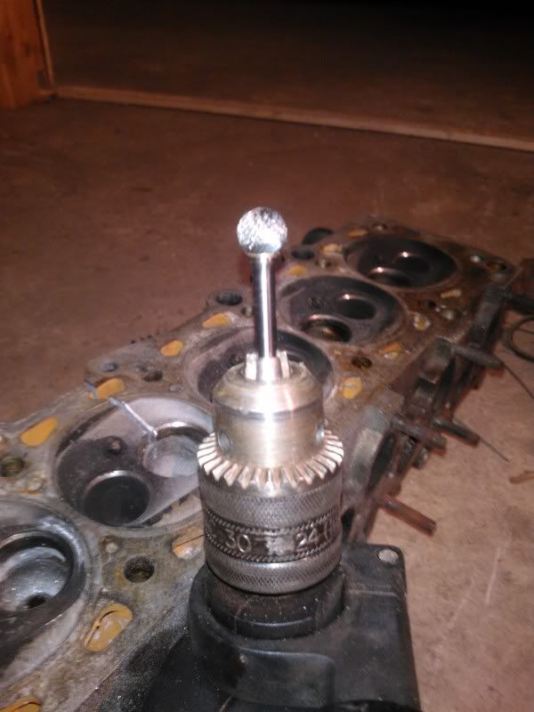
Managed to successfully blend the valve seat/head interface all around the valve (no pics) as well as smooth out the short side radius 'steps', though am stumped as to how to whittle down the valve guide support casting as I can't get near it with my current tooling. Any ideas? Tony?! 
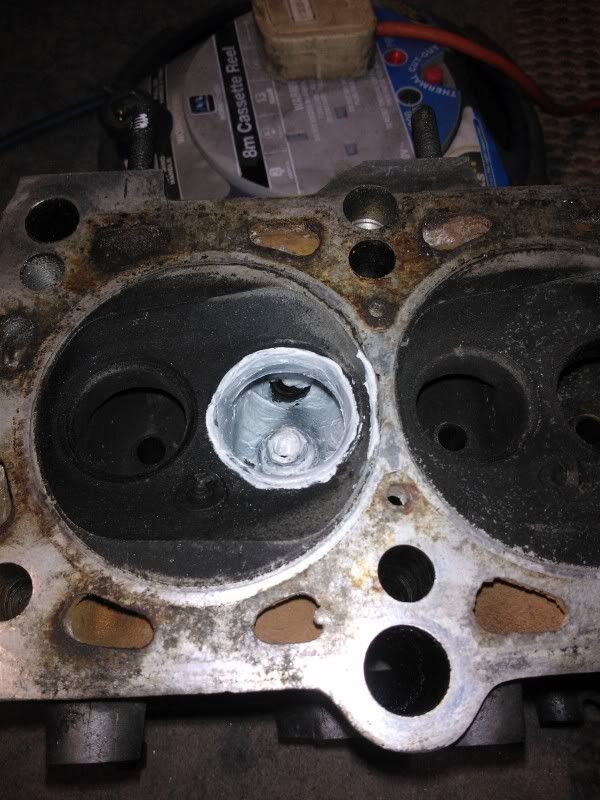
Lastly I took a silicone mould of one of the un-touched ports as while I hope I'm be making them visibly better it's always nice to have a record of where you started: ![]() Cheerss, Matt |
|
|
|
![]() |
| Bookmarks |
|
|